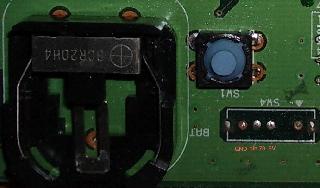
| The whole pin 79 setup is kind of weird. Underneath VDP2 there is a pull-down resistor (R29) and a jumper to 5V (JP1), so far so usual - leaving JP1 open means the system runs at 50Hz, bridging it makes it run at 60Hz. However, under SW4 there is a jumper between the pin79 line and SW4's GND (JP19) but even more strange SW4 and JP19 are connected to GND via JP16, but JP16 is bridged by a PCB trace between the solder pads. I'm guessing JP19 and JP16 are leftovers from an earlier board layout the designers didn't feel warranted the trouble of redoing, because as-is it only presents an opportunity to short-circuit the board. |