| Home | Forums | What's new | Resources | |
| VDP2 questions |
| AntiPasta - Apr 3, 2003 |
| 1 | 2 | 3 | Next |

| AntiPasta | Apr 3, 2003 | ||
| yeah I'm pretty darn certain VDP2 holds a lot of untapped power... but I should add the PSX' GPU is a LOT easier to program <_< | |||
| TakaIsSilly | Apr 3, 2003 | ||
| Hell, yeah. But where's the fun in that? ^o^ | |||
| AntiPasta | Apr 4, 2003 | ||
| okay I've looked up the map offset register (MPOFN). The bit layout, however, makes no sense to me! There are these 3-bit groups like N0MP8, NOMP7 and N0MP6. Now the documentation isn't very clear on this, how is an address formed from these values? Are they somehow combined with the MPxxN0 registers? And what are these planes? | |||
| antime | Apr 4, 2003 | ||
| The bits are explained on page 86 of the doc (page 104 of the PDF). For NBG0, use bits N0MP6-N0MP8. The bits are numbered 6-8 because for tiled modes they are combined with the Normal Map Screen Scroll Registers, which hold bits 0-5. For bitmaps the start address seems to be 0x20000*offset bit value. | |||
| AntiPasta | Apr 17, 2003 | ||
okay I wrote some more code to deal with the VDP2... however I keep getting stuff like this: Now here's what I write to the registers: -%1000000000010000 to TVMD -0 to EXTEN -0x101 to BGON -0 to LCTAU and LCTAL -%110010 to CHCTLA -0 to CHCTLB -0 to MPOFN And then I blast some test pixels to $25E00000 (I believe this is the greeny bar you see) - but instead of a 'clean' screen with some the lines of pixels that I wrote I get all this garbage - what did I do wrong? | |||
| AntiPasta | Apr 18, 2003 | ||
| bump I'm sorry I have to do this, but I desperately need some help on this for the contest. Please don't ban me  | |||
| ExCyber | Apr 18, 2003 | |||
I may be mistaken, but it looks like your write to BGON enables NBG2, and you never configure it anywhere else, so your writes to VDP2 RAM are probably translating into garbage on NBG2. | ||||
| AntiPasta | Apr 19, 2003 | |||
That's a hex value (stupid of me to mix number systems), so it sets bit 0 and bit 8... by the way printf told me to try some other values for MPOFN, and setting it to 3 got me a clear screen (so apparently the garbage comes from VRAM and sits somewhere in the lower region)... | ||||
| ExCyber | Apr 19, 2003 | ||
| If you're still interested in finding out what caused this, page 265 (PDF page 283) of the VDP2 doc has a table of all data structures that use VRAM, and their corresponding configuration registers. You might want to try setting it up so that nothing shares the same address and then run through a loop throwing your test pixels at each area and waiting a few seconds or some similar diagnostic. | |||
| paul_met | Oct 14, 2019 | ||
| In order not to create a new topic, I’ll ask here. Is it possible to make layers 1 and 2 translucent for layer 3 at the same time (when I see layer 3 through layers 1 and 2)? If it possible, what should be the settings for all layers. | |||
| fafling | Oct 19, 2019 | ||
| It is possible only in standard resolution. I suppose that layers are numbered in decreasing priority order, layer 1 has the highest priority and 3 the lowest. I also suppose that layer 3 has no transparent pixels. Otherwise, replace layer 3 in the following explanation by whatever mix of layers is below layers 1 and 2. Page numbers are those of VDP2 manual. So you have to :
Not the simplest subject for my first post here ! | |||
| paul_met | Oct 20, 2019 | |||
This is exactly the effect I want to achieve. But so far it does not work out. Here are screenshots with layers and layer settings. As you can see, when you turn on the translucency for the topmost layer, the second layer becomes opaque and the third layer is not visible through it. 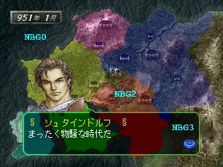 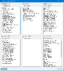 | ||||
| fafling | Oct 20, 2019 | ||
| You're using a palette layer as layer 3. Is color RAM mode set to 0 ? It can be checked in Kronos v1.7.0, where it is added in General info of VDP2 debug window, under Sprite stuff. | |||
| David Gámiz Jiménez | Oct 20, 2019 | ||
| From I know and see of vdp2. It not can blend more than once layer between other. In simply words. Only one layer can be have translucy, not multilayer. | |||
| paul_met | Oct 20, 2019 | ||||||
That's why I was embarrassed, why the developers did not make the dialog box translucent on the screen with the global map (in other cases, the dialog box is translucent).
Yes . There are no different visually from CRM=0 and CRM=2. But when CRM= 2 is activated, it turns out like this. | |||||||
| fafling | Oct 20, 2019 | ||
| @David Gámiz Jiménez... Sure you can have multilayer blending, that's what extended color calculation is for. Check Sonic R, it uses that for the water ripples and reflections in the first stage. @paul_met... You mean color RAM mode 0 and 1 are not different visually. Mode 2 is different because it uses 24 bit colors instead of 15 bit colors like the other 2. The difference of mode 0 is that colors are mirrored so it contains twice as less colors than mode 1. It's probably to enable a faster access to the color RAM than in mode 1. I see that the mosaic effect is enabled on NBG0, it could be what prevents the blending effect in the emulator. Since there's no such restriction in the manual, could be an emulator bug. Have you tested on the console ? | |||
| paul_met | Oct 21, 2019 | |||
No, I don’t have the original hardware. But I tried on another emulator (SSF) and double translucency works! But it works only if Color Ram Mode = 1. So, you are right, Yabause have a bug with ECC. Anyway it is strange why developers did not want to use ECC... | ||||
| 1 | 2 | 3 | Next |